USER’S GUIDE for the
LRD4100
The LION PRECISION LRD4100 LABEL SENSOR is an electronic sensor used to monitor label registration and/or count labels. The NPN and PNP type outputs will indicate the leading or trailing edge of the label. Output polarity is wire selectable.
Gaps between labels of less than 2.5 mm (0.1″) may not be detected reliably. Metal labels or labels with no gap will not be detected.
The LRD4100 missing label sensor has very stringent mounting requirements to assure reliable operation. An unvarying parallelism between the sensor surface and the baseplate over which the web travels is critical.
Mounting the Sensor
Mount the sensor with the active end parallel to a mechanically stable, electrically conductive reference plate. The distance from the sensor to the plate must be 0.813 ±0.076mm (0.032 ±0.003″) and parallelism must be within 0.05mm (0.002″). The mounting hardware must be stiff enough to maintain these specifications throughout the operating environment thermal range. There must be electrical conductivity between the sensor body and reference plate. For more detail, see Lion Precision TechNote LT04-0020 Mounting LRD4100 Label Sensors available at www.lionprecision.com
Mount the sensor so label material completely covers the active area of the sensor.
Warnings:
- Sensor body is connected to Ground.
- Sensors must not be attached to voltages in excess of 30VRMS or 60VDC
- All power must be off when installing the sensor.
- Use of the equipment in any other manner may impair the safety and EMI protections of the equipment.
LRD4100 Wiring
|
Wire Color |
Connection |
Notes |
|
Red |
Vin (11-28V) |
50mA max. |
|
Black |
Ground |
Connected to sensor body |
|
Green |
NPN Output |
150mA max. |
|
Blue |
PNP Output |
150mA max. |
|
Brown |
Output Polarity |
+V or Ground |
|
Warning: Brown wire must be connected to +V or Ground for reliable operation. |
||

Setup Procedure
- Remove all material from sensor.
- Turn gain pot four (4) turns counter-clockwise.
- Turn gain pot two (2) turns clockwise.
- Turn zero pot until zero LED just turns on. ( if LED is on, rotate counter clockwise, if LED is off rotate clockwise)
- Insert material into sensor. Move material through sensor and observe the gain If the gain LED flashes between gap and label, setup is complete. If LED fails to flash, turn gain pot clockwise while moving labels through, until the LED flashes then continue turning ½ turn. Sensor is now ready to run.
Notes:
1) Some inks, usually black, have a high carbon content. These inks behave like metal and may not work reliably with the LRD4100.
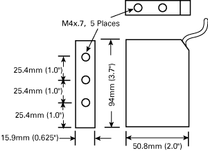
Output and Mechanical Detail
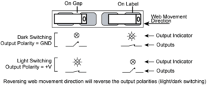
Light/Dark switching is affected by the direction of label movement and the Output Polarity connection. Output descriptions below are for web direction indicated in the illustration and are reversed for web movement in the other direction.


Specifications
|
Power supply |
Voltage |
11-28 V (reverse polarity protected) |
|
Current |
50mA |
|
|
Response time |
on or off |
20µs max |
|
Switching Frequency |
10kHz max |
|
|
Output |
Output Current (sinking or sourcing) |
150mA max (overload protected) |
|
Switching output |
PNP (sourcing) or NPN (sinking), |
|
|
Temperature |
Operating Range |
40°F to 140°F (4°C to 60°C) |
|
Protections |
Supply |
Inverse Polarity Protection |
