Copyright © 2007 Lion Precision. www.lionprecision.com
Summary
This TechNote describes the nature and magnitude of error voltages generated by off-center positioning of thread-detection probes and mechanical limitations for centering errors.
Thread Sensing Probe Centering Errors
Synopsis
Limiting centering errors to 0.010″ (0.25mm) provides reliable operation with all probes and hole sizes.
Larger holes allow for more centering error.
Ferrous materials allow for significantly more centering error than nonferrous materials.
Thread sensors generate different output voltages for tapped versus untapped holes. The presence or absence of threads is determined by the this voltage difference. Voltage differences are also generated by off-center probe insertion. For reliable operation, these off-center voltage changes must be less then the tapped/untapped voltage changes.
Mechanical Considerations
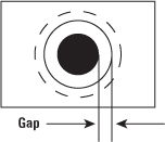
Severe centering errors may cause the probe to crash into the target. Nonferrous sensor diameters are about 85% of the hole size, while ferrous sensors are about 65% of the hole size. The table below shows typical gap sizes:

|
||||||||||||||||||||||||||||||||||||||||||
|
Nonferrous Materials |
||
|
Hole Size |
Probe |
Gap (inch/mm) |
| M5 x .8 | T5BZ | 0.018/0.46 |
| M6 x 1 | T6BZ | 0.018/0.46 |
| M7 x 1 | T7BZ | 0.018/0.46 |
| M8 x 1.25 | T8BZ | 0.018/0.46 |
| M8 x 1 | T8BZ | 0.024/0.60 |
| M10 x 1.5 | T10BZ | 0.018/0.46 |
| M10 x 1.25 | T10BZ | 0.024/0.61 |
| M12 x 1.75 | T12BZ | 0.018/0.46 |
| M12 x 1.25 | T12BZ | 0.027/0.68 |
| M16 x 1.5 | T16BZ | 0.018/0.46 |
| M16 x 2 | T16BZ | 0.028/0.71 |
Protective Mounting
Spring-loaded probe mounts can be used to protect probes from damage in case of crash. Two models are available for different probe sizes:
|
Model: |
SN-08 |
SN-12 |
SN-18 |
| Internal Thread (must match probe) |
M8x1 (T5-8) |
M12x1 (T10-12) |
M18x1 (T16) |
| External Thread | M16x1.5 | M22x1.5 | M30x1.5 |
| Maximum Extension | 0.35″ (8.9mm) | 0.41″ (10.4mm) | 0.49″ (12.4mm) |
Electrical Considerations
Basic Operation
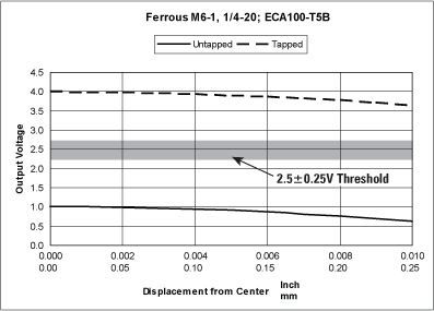
Thread sensors generate different voltages for threaded vs. unthreaded holes. A threshold voltage is set halfway between these two voltages using the switch adjustment (2.5V in the example below). The system indicates an unthreaded hole when the output is below the threshold.
As the probe is moved off-center, the voltage output decreases. For reliable operation, the unthreaded voltage must remain 0.25V above the threshold voltage (see sample figure below).

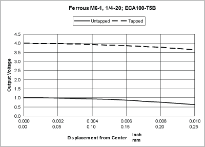
Ferrous materials
The presence/absence voltage difference is large with ferrous materials. This allows for significant off-center voltages without affecting performance.
Off-center amounts of 0.010″ (0.25mm) generate voltage changes amounting to 2%-5% of the presence/absence voltage change.
Sample Ferrous Chart (charts for all probes are available in the pdf version [188k])

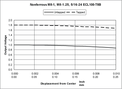
Nonferrous materials
The presence/absence voltage difference is small with nonferrous materials. Control of probe centering is of greater concern with nonferrous materials.
Off-center amounts of 0.010″ (0.25mm) generate voltage changes about 10%-25% of the presence/absence voltage change.
Sample Nonferrous Chart (charts for all probes are available in the pdf version [188k])

