Summary
This TechNote describes the extent and nature of measurement errors as a result of a capacitive probe’s sensing surface not being parallel to the target surface.
Error Sources: Capacitive Probe/Target Angle

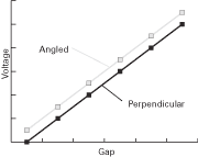
Systems are calibrated with the probe perpendicular to the target surface. As that angle changes, the output will show a DC (offset) shift relative to the actual gap from the probe’s center axis to the target.
- Probe angle introduces a positive DC (offset) shift in the output causing the target to appear closer.
- Gain (scaling) error due to probe angle is insignificant in comparison to DC (offset) shift.
In addition to the Probe/Target angle, the magnitude of the error is dependent on:Sensor Radius,Probe/Target Gap,Sensor Geometry.
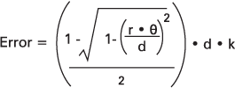
Error [m] is described by this function:

Download PDF File Where:
r = radius [meters] of probe sensor area
d = probe/target gap, directly under the probe center axis [meters]
Θ = probe/target angle [radians]
k = experimentally determined constant to account for field fringing errors
Typical k values are around 5.
Example 1: 0.5mm sensor radius, at 0.25mm gap, with a 0.0002 radian angle produces an error of approximately 0.05nm.
Example 2: 3mm sensor radius, at 0.75mm gap, with a 0.03 radian angle produces an error of approximately 13µm.
